Function check / self test
All Cable Avoidance equipment should be checked before use to ensure that it is operating as intended.
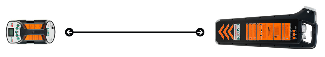
The C.Scope new XL2 and XL4 range of products automatically check themselves through a feature called Automatic Daily Self Test (ADST) so do not require Function Checking.
NON-XL2 or XL4 products do not have the Automatic Daily Self Test feature so do need to be Function Checked. These products can be checked by running through a set of Manual Function Checks.
C.Scope have integrated a fully Automatic Daily Self Test (ADST) into the XL2 and XL4 range of Products which means these products effectively function check themselves every day when the product is switched on before use.
The products that feature Automatic Daily Self Testing are:
CXL4 Cable Avoidance Tool
CXL4-D Cable Avoidance Tool
CXL4-DBG Cable Avoidance Tool
DXL4-D Cable Avoidance Tool
DXL4-DBG Cable Avoidance Tool
SGV4 Signal Generator
MXL4-D Precision Pipe and Cable Locator
MXL4-DBG Precision Pipe and Cable Locator
This is built into the unit and the result of the ADST is stored on the product everyday. ADST ensures that the locator is fully tested and functional before it is used.
If required, proof that the Locator/Cable Avoidance Tool/Signal Generator/Transmitter has passed the ADST at any particular date and time can be checked by downloading the relevant Product Validation Certificate from the unit and printing out on a PC using the C.Scope PC Toolkit. Certificates can be downloaded as often as needed and at no charge.
It is recommended that the operation of the following products is checked before use:
CXL3 Cable Avoidance Tool
DXL3 Cable Avoidance Tool
SGA3 Signal Generator
SGA4 Signal Generator
SGV4 Signal Generator
These checks can be done manually or using the Function Checker.
LOCATOR FUNCTION CHECKS
It is recommended that the operation of the C.Scope Cable Avoidance Tool and Signal Generator is checked before use.
These checks DO NOT guarantee full system performance. The Cable Avoidance Tool and Signal Generator should be returned to the manufacturer or an approved agent for recalibration every 12 months.
Battery Condition
Check by depressing the On/Off switch beneath the handle. The display will show at least one solid segment if the batteries are ok. Ensure power on tone is heard.
Power Mode
Select Power Mode. Set Sensitivity fully clockwise and point the body of the C.Scope Cable Avoidance Tool at a fluorescent light from a distance of 1m. Switch the light on. A loud tone should be heard and the display should read greater than 50% full scale. Reducing the sensitivity should cause the displayed reading to reduce and the tone to cut out.
Radio Mode
Select Radio Mode. Set the Sensitivity fully clockwise and, from a distance of less than 0.25m, point the unit at a metal conductor of length greater than 100m (for example a pipe or cable). A warbling tone should be heard. The display should read greater than 50% full scale.
Generator Mode
Locate an outdoor test area that is free from extraneous fields resulting from overhead and underground cables. The area should also not be near fences, steel framed buildings, or on reinforced concrete as the signal will be reduced.
Place the Signal Generator on the ground in the normal orientation and switch on – a tone should be heard. Set to Continuous and ensure highest output power is selected.
With the C.Scope Cable Avoidance Tool in the orientation shown, and Sensitivity rotated
| Distance | Mode | Audio | Meter |
|---|---|---|---|
| 6 Meters | Generator | Present | Full Scale |
| 12 Meters | Generator | Less than 6 metres | Less than full scale |
| 6 Meters | Radio | Present | – |
| 6 Meters | Power | – | – |
DEPTH MEASUREMENT CHECKS
An area free of services, metal structures, etc should be chosen (beware of reinforced car parks). A search with the C.Scope Cable Avoidance Tool in all 3 modes will help confirm the absence of other services. An insulated cable or wire 20m+ (not supplied) is laid out on the ground surface and the far end connected to a ground stake and earthed. The near end is connected to the red Connected Mode lead.
The black ground Lead should be laid at right angles to the 20m wire and earthed at the far end with a ground stake. The plug should be inserted in the connector on the Signal Generator.
The Signal Generator is turned on with lowest power, and continuous mode selected. The C.Scope Cable Avoidance Tool should then be held vertically above the longer wire, approximately midway along it, ie. 10m from the Signal Generator.
The depth can then be measured. It is best to make a few readings at different depths. (Beware – metal step ladders affect the accuracy!)
SIGNAL GENERATOR FUNCTION CHECKS
Battery Condition
Select Continuous. Good batteries will be shown by a loud clear audio tone. Bad batteries give an interupted audio tone. On the SG-V the display will show at least one solid segment if the batteries are ok.
Induced Mode
This can only be checked in conjunction with a C.Scope Avoidance Tool as described in Locators Function Check.
If the unit does not meet the results required, repeat the test with another C.Scope Cable Avoidance Tool to determine whether the Signal Generator is suspect.
Connected Mode
Set the minimum output level, insert the connection lead and the long earth lead and then connect the red lead to the long earth lead to create a short circuit. The pitch should change to a low tone.
The leads should be arranged to create an open loop on the ground of approximately 1m diameter. Check that a signalcan be detected by the Cable Avoidance Tool (in Generator Mode) when pointed closely at the loop.
